Definition:
1. (Programmable Logic Controller) A programmable microprocessor-based device that is used in discrete manufacturing to control assembly lines and machinery on the shop floor as well as many other types of mechanical, electrical and electronic equipment in a plant. Typically RISC based and programmed in an IEC 61131 programming language, a PLC is designed for real-time use in rugged, industrial environments. Connected to sensors and actuators, PLCs are categorized by the number and type of I/O ports they provide and by their I/O scan rate.
In the late 1960s, PLCs were first used to replace the hardwired networks of relays and timers in automobile assembly lines, which were partially automated at that time. The programmability of the PLC enabled changes to be effected considerably faster.
2. A programmable logic controller (PLC) or programmable controller is a digital computer used for automation of electromechanical processes, such as control of machinery on factory assembly lines, amusement rides, or lighting fixtures. PLCs are used in many industries and machines. Unlike general-purpose computers, the PLC is designed for multiple inputs and output arrangements, extended temperature ranges, immunity to electrical noise, and resistance to vibration and impact. Programs to control machine operation are typically stored in battery-backed or non-volatile memory. A PLC is an example of a hard real time system since output results must be produced in response to input conditions within a bounded time, otherwise unintended operation will result.
PLC Topics
The main difference from other computers is that PLCs are armored for severe conditions (such as dust, moisture, heat, cold) and have the facility for extensive input/output (I/O) arrangements. These connect the PLC to sensors and actuators. PLCs read limit switches, analog process variables (such as temperature and pressure), and the positions of complex positioning systems. Some use machine vision. On the actuator side, PLCs operate electric motors, pneumatic or hydraulic cylinders, magnetic relays, solenoids, or analog outputs. The input/output arrangements may be built into a simple PLC, or the PLC may have external I/O modules attached to a computer network that plugs into the PLC.
System scale
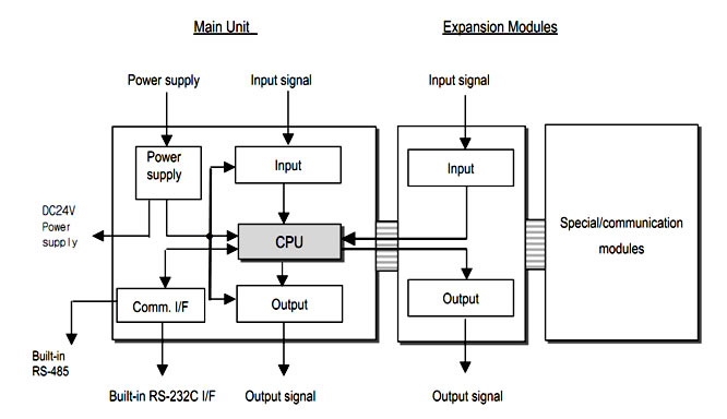
A small PLC will have a fixed number of connections built in for inputs and outputs. Typically, expansions are available if the base model has insufficient I/O.
Modular PLCs have a chassis (also called a rack) into which are placed modules with different functions. The processor and selection of I/O modules is customised for the particular application. Several racks can be administered by a single processor, and may have thousands of inputs and outputs. A special high speed serial I/O link is used so that racks can be distributed away from the processor, reducing the wiring costs for large plants.
User interface
PLCs may need to interact with people for the purpose of configuration, alarm reporting or everyday control.
A Human-Machine Interface (HMI) is employed for this purpose. HMIs are also referred to as MMIs (Man Machine Interface) and GUIs (Graphical User Interface).
A simple system may use buttons and lights to interact with the user. Text displays are available as well as graphical touch screens. More complex systems use programming and monitoring software installed on a computer, with the PLC connected via a communication interface.
Communications
PLCs have built in communications ports, usually 9-pin RS-232, but optionally EIA-485 or Ethernet. Modbus is usually included as one of the communications protocols. Other options include various fieldbuses such as DeviceNet or Profibus. Other communications protocols that may be used are listed in the List of automation protocols.
Most modern PLCs can communicate over a network to some other system, such as a computer running a SCADA (Supervisory Control And Data Acquisition) system or web browser.
PLCs used in larger I/O systems may have peer-to-peer (P2P) communication between processors. This allows separate parts of a complex process to have individual control while allowing the subsystems to co-ordinate over the communication link. These communication links are also often used for HMI devices such as keypads or PC-type workstations.
Programming
PLC programs are typically written in a special application on a personal computer, then downloaded by a direct-connection cable or over a network to the PLC. The program is stored in the PLC either in battery-backed-up RAM or some other non-volatile flash memory. Often, a single PLC can be programmed to replace thousands of relays.
Initially most PLCs utilized Ladder Logic Diagram Programming, a model which emulated electromechanical control panel devices (such as the contact and coils of relays) which PLCs replaced. This model remains common today.
IEC 61131-3 currently defines five programming languages for programmable control systems: FBD (Function block diagram), LD (Ladder diagram), ST (Structured text, similar to the Pascal programming language), IL (Instruction list, similar to assembly language) and SFC (Sequential function chart). These techniques emphasize logical organization of operations.
While the fundamental concepts of PLC programming are common to all manufacturers, differences in I/O addressing, memory organization and instruction sets mean that PLC programs are never perfectly interchangeable between different makers. Even within the same product line of a single manufacturer, different models may not be directly compatible.